Print this page

Magneto Ignition
Home
Air Filter
Carburettor
Compression Ratio
Crankcase Stuffing
Cylinder Head
Electronic Ignition
Engine Ports
Exhaust Silencer
Expansion Chamber
Magneto Ignition
Spark Plug
Transmission Roller

Introduction

THE Magneto Coil on the VeloSoleX S 3800 is prone to failure if the engine is driven at speeds higher than 4000 RPM. It fails due to heat caused by excessive current in the Primary Winding causing insulation breakdown and shorted turns.

The Rotor is a 4-Pole Magnetic System (North-South-North-South), so there are 2 electrical cycles (2 current sinewaves) generated per engine revolution. The Lighting Coil current is thus at twice the frequency of a 2-Pole Magnetic System (North-South) and results in reduced Headlight beam flickering at low speed.

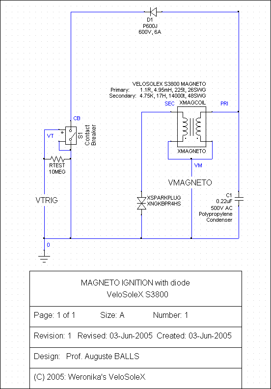
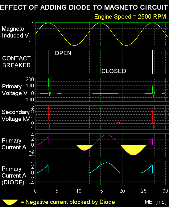
The Magneto Coil also generates 2 electrical cycles per engine revolution. The Contact Breaker opens halfway during the 1st positive half-cycle just as the current has reached its peak and closes during the following negative cycle has started. It then remains closed for one electrical cycle. When the current of about 3A is broken suddenly by the Contact Breaker, a voltage (back emf) transient of 200V is generated across the winding which is stepped up to 12KV in the Secondary Winding (by transformer action) to fire the Spark Plug. Unfortunately at speeds higher than 4000 RPM, the Primary Winding current can rise above 4A and heat-damage the Magneto Coil.


Magneto Coil Modification

If the unwanted negative current half cycles can be blocked then the electrical heating of the coil can be reduced without affecting performance. To do this:

  1. Remove Magneto Rotor using a Magneto Rotor Extractor
  2. Disconnect the Magneto Coil wire from the Contact Breaker nut and reconnect it to the Condenser nut.
  3. Crimp and solder Electrical Eye Connectors to both ends of a P600J Silicon Rectifier Diode and connect it between the Condenser nut and the Contact Breaker nut making sure that the Cathode end (Stripe) of the Diode goes toward the Contact Breaker.
  4. If the engine refuses to start, the Magneto Coil may have been manufactured with the opposite polarity, in which case, reverse the polarity of the Diode.

P600J


Diode Fitted


An additional benefit is that electrical wear of the Contact Breaker is reduced significantly.


Computer Simulation

FOR those who wish to view a Computer Simulation of my Magneto Ignition with Diode system, I am including the schematic diagram MAGNETO.SCH (for personal use only):

Magneto

and MAGNETO.CIR for the program TopSPICE (PSPICE):

TopSPICE Simulation of MAGNETO IGNITION with Diode

.PARAM RPM=2500
.PARAM Vpeak=10.5
.PARAM Freq={RPM/60*2}
.PARAM Period={1/(RPM/60)}
.PARAM Open={Period/8}
.PARAM Duration={Period*0.275}
VMAGNETO VM 0 SIN (0
{Vpeak} {Freq})
VTRIG VT 0 PULSE (1 0
{Open} 1nS 1nS {Duration} {Period} 0)
RTEST VT 0 10MEG               
;Return path

C1 PRI 0 0.22uF                ;0.22uF 500V AC POLYPROPYLENE CONDENSER
D1 PRI CB DP600J               
;P600J 600V 6A Silicon Rectifier Diode
S1 CB 0 VT 0 SW                
;CONTACT BREAKER

XMAGCOIL PRI VM SEC VM XMAGNETO;MAGNETO COIL +PRI GND +SEC GND
RLEAD SEC 1 1R                 ;
HT LEAD RESISTANCE
LLEAD 1 2 25uH                 ;
HT LEAD INDUCTANCE
CLEAD 2 0 70pF                 ;
HT LEAD CAPACITANCE

XSPARKPLUG SPARK 0 XNGKBPR4HS  ;NGK BPR4HS SPARK PLUG
RPLUG 2 3 5K                   
;SPARK PLUG RESISTANCE
LPLUG 3 SPARK 10nH             
;SPARK PLUG INDUCTANCE
CPLUG SPARK 0 100pF            
;SPARK PLUG CAPACITANCE

#AUTOPLOT 1 V(VM)
#AUTOPLOT 2 {1-V(VT)}
#AUTOPLOT 3 V(PRI)
#AUTOPLOT 4 V(SEC)
#AUTOPLOT 5 I(D1)

.TRAN 0.5mS 35mS 0mS 0.5mS
.SAVE

.MODEL DP600J D                ;P600J 600V 6A Silicon Rectifier Diode
+IS=1.19449e-08 RS=0.00284884 N=1.19832 EG=1.3
+XTI=0.5 BV=630 IBV=0.0001 CJO=3.13475e-10
+VJ=1.00996 M=0.459839 FC=0.5 TT=2.04804e-06
+KF=0 AF=1

.SUBCKT XMAGNETO 1 2 3 4       ;MAGNETO COIL +PRI GND +SEC GND
.PARAM RSEC=4750 LLEAK=282uH RPRI=1.1R CINTWIND=50pF TNRATIO=62.2
RS 6 3
{RSEC}
E3 5 4 VALUE
{V(7,2)*TNRATIO}
LL 8 7
{LLEAK}
CSP 1 3
{CINTWIND}
VM 5 6 DC 0
.PARAM LCORE=4.95MH FEDDY=5.05KHZ
E2 13 0 VALUE
{V(8,2)/V(12,0)}
E1 12 0 TABLE
{ABS(I(V1))}
+ (0,1) (.5,1) (.75,.993) (1.25,.892)
+ (1.75,.856) (2.25,.856) (2.75,.793)
+  (3.25,.772) (3.75,.735) (4.25,.674)
+ (4.75,.634) (5.25,.569) (5.75,.535)
G2 8 11 14 0 1
C1 15 14
{LCORE}
V1 11 2 DC 0
G1 0 14 13 0 1
R2 0 14 100MEG
R1 0 15
{1/(6.283*FEDDY*LCORE)}
R3 2 8 100MEG
G3 7 2 VALUE
{I(VM)*TNRATIO}
RP 1 8
{RPRI}
.ENDS XMAGNETO

.SUBCKT XNGKBPR4HS 1 2        ;NGK BPR4HS SPARK PLUG
.MODEL D1N4148 D(Is=2.682n N=1.836 Rs=.5664 Xti=3 Eg=1.11 Cjo=4p
+ M=.3333 Vj=.5 Fc=.5 Bv=100 Ibv=100u Tt=11.54n)
.PARAM VGLOW=1500 VARC=150 ISUS=2mA VBRKDWN=12000 IARC=200mA
D3 10 11 DZARC
SWSARC 3 10 9 0 SWARC
.MODEL SWARC VSWITCH Roff=50MEG Ron=5R Voff=0V Von=10V
RT1 7 0 50R
DT2 8 9 D1N4148
.MODEL DZGLOW D (BV={VGLOW} IS=1uA RS=5R IBV=10uA)
EBRKDWNCTRL 6 0 VALUE
{IF(ABS(V(1,2))>VBRKDWN|ABS(I(VSENSE))>ISUS,12,0)}
.MODEL DZARC D (BV={VARC} IS=1uA RS=5R IBV=10uA)
D4 5 11 DZARC
EARC_CTRL 8 0 VALUE
{IF(ABS(I(VSENSE))>IARC,12,0)}
D2 5 4 DZGLOW
VSENSE 5 2 DC 0
CT2 9 0 0.1uF
RT2 9 0 50R
CT1 7 0 0.25uF
SWSBV 1 3 7 0 SW_SPK
.MODEL SW_SPK VSWITCH Roff=50MEG Ron=5R Voff=0V Von=10V
D1 3 4 DZGLOW
DT1 6 7 D1N4148
.ENDS XNGKBPR4HS

.END

The graph below shows the effect of the Diode (WITHOUT SPARK PLUG FITTED):


Magneto Graph


Maintenance

THE Contact Breaker electrical contacts are made from low resistance Platinum-Iridium (used for low-voltage Magneto Ignition systems) and not the harder, higher resistance Tungsten type (used for 6V or 12V Kettering battery systems) and should therefore NEVER be polished with an abrasive file. Instead, insert a folded strip of 1200 Grade Wet & Dry Abrasive Paper between the closed contacts and very lightly pull in and out, then insert a folded strip of clean white paper moistened with Iso-Propyl Alcohol. Finally, make sure that no paper is left between the contacts.

The Felt Pad on the Contact Breaker should be moistened with a few drops of Light Engine Oil and the excess removed with a paper towel.

The HT Lead should be replaced with a multi-strand copper type and soldered directly to the HT Output (brass tab) of the Magneto Coil. Crimp and solder an Electrical Eye Connector to the end that goes to the Spark Plug. To prevent moisture or damp affecting the HT Output (brass tab), it should be coated with High-Temperature Epoxy Resin.


Go to top of page

VELOSOLEX is a trademark of VELOSOLEX AMERICA, LLC
e-SOLEX, SOLEX and SOLEXINE are trademarks of Societie SINBAR - Groupe CIBLE
 

Copyright © 2008 BRIAN'S VELOSOLEX. All rights reserved. This is a personal website containing information for and by VeloSoleX enthusiasts. It is not intended to replace any official information and whilst every effort is made to ensure the accuracy of all published information no guarantee is offered nor liability accepted for any loss or damage that may arise from any errors or omissions.