|
FOR those who wish to view a Computer
Simulation
of my CDI (Capacitor Discharge Ignition) system,
I am including the schematic diagram CDI.SCH (for
personal use only):

and CDI.CIR for the program TopSPICE (PSPICE):
TopSPICE Simulation of CDI
(CAPACITOR
DISCHARGE IGNITION)
.PARAM
RPM=2500
.PARAM
Vpeak=290
.PARAM
Freq={RPM/60*2}
.PARAM
Period={1/(RPM/60)}
.PARAM
Open={Period/8}
.PARAM
Duration={Period*0.275}
VEXCITER
0 VM SIN (0 {Vpeak}
{Freq})
VTRIG VT
0 PULSE (1 0 {Open}
1nS 1nS {Duration}
{Period} 0)
RTEST VT
0 10MEG ;Return
path
R1 2 CB 22K ;CURRENT-LIMITING
RESISTOR
R2 3 GATE 220R
;CURRENT-LIMITING
RESISTOR
R3 GATE 0 470R
;TO
PREVENT FALSE TRIGGERING OF SCR
C1 CB 3 22nF ;GATE
TRIGGER CAPACITOR
C2 GATE 0 10nF ;TO
PREVENT FALSE TRIGGERING OF SCR
C3 VCHARGE PRI 0.47uF ;MAIN
DISCHARGE CAPACITOR
D1
1 VCHARGE D1N4007 ;POSITIVE
CYCLE DIODE
D2
2 1 D1N4007 ;NEGATIVE
CYCLE DIODE
D3
0 GATE D1N4007 ;FAST-CHARGE DIODE
FOR C1
D4
PRI 0 DP600J ;DISSIPATION
DIODE
XEXCOIL VM 1 XEXCITER
;EXCITER
COIL (9 x 250t = 2250t)
XDIAC1
CB 0 XBR100 ;BR100
(DB3) 32V 2A DIAC
XSCR1
VCHARGE GATE 0 XTIC106M ;SCR
TIC106M A G K - 600V 4A
S1
CB 0 VT 0 SW ;CONTACT
BREAKER
XIGNCOIL PRI 0 SEC 0 XIGNITIONCOIL;IGNITION
COIL +PRI GND +SEC GND
RLEAD
SEC 4 1R ;HT
LEAD RESISTANCE
LLEAD
4 5 25uH ;HT
LEAD INDUCTANCE
CLEAD
5 0 70pF ;HT
LEAD CAPACITANCE
XSPARKPLUG SPARK 0 XNGKBPR4HS
;NGK BPR4HS
SPARK PLUG
RPLUG 5 6
5K ;SPARK
PLUG RESISTANCE
LPLUG
6 SPARK 10nH ;SPARK
PLUG INDUCTANCE
CPLUG
SPARK 0 100pF ;SPARK
PLUG CAPACITANCE
#AUTOPLOT
1 V(VM)
#AUTOPLOT
2 {1-V(VT)}
#AUTOPLOT
3 V(CB)
#AUTOPLOT
4 V(GATE)
#AUTOPLOT
5 V(VCHARGE)
#AUTOPLOT
6 V(SEC)
.TRAN
0.5mS 40mS 0mS 0.5mS
.SAVE
.MODEL
D1N4007 D ;1N4007
1000V 1A Silicon Rectifier Diode
+IS=1.19449e-08
RS=0.00284884 N=1.19832 EG=1.3
+XTI=0.5 BV=630 IBV=0.0001
CJO=3.13475e-10
+VJ=1.00996 M=0.459839 FC=0.5 TT=2.04804e-06
+KF=0
AF=1
.MODEL
DP600J D ;P600J
600V 6A Silicon Rectifier Diode
+IS=1.19449e-08
RS=0.00284884 N=1.19832 EG=1.3
+XTI=0.5 BV=630 IBV=0.0001
CJO=3.13475e-10
+VJ=1.00996 M=0.459839 FC=0.5 TT=2.04804e-06
+KF=0
AF=1
.SUBCKT XBR100
1 2 ;BR100
(DB3) 32V 2A DIAC
RS
1 N006 10
RV N002 N004 225K ;Vbrkdwn
= 32V (RV changes it)
R1
N006 N002 10K ;Sets
Ibo to 60uA
R2 N004
2 10K ;Sets
Ibo to 60uA
Q4 N002
N005 2 0 PNP
Q2 N004 N003 N006 0 PNP
Q1 N003 N004
2 0 NPN
Q3 N005 N002 N006 0 NPN
D5 N002 N005 D
D6
N004 N003 D
.MODEL
NPN NPN(BF=20 TF=5u)
.MODEL PNP
PNP(BF=2 TF=5u)
.MODEL D
D
.ENDS XBR100
.SUBCKT XTIC106M
1 2 3 ;SCR
TIC106M A G K - 600V 4A
QP
6 4 1 QPOUT
QN 4 6 5 QNOUT
RF
6 4 133MEG
RR 1 4 88.9MEG
RGK
6 5 1.12K
RG 2 6 46.2
RK
3 5 16.2M
DF 6 4 DZF
DR
1 4 DZR
DGK 6 5 DZGK
.MODEL
DZF D (IS=1.6F IBV=900N BV=600 RS=20MEG)
.MODEL
DZR D (IS=1.6F IBV=900N BV=800)
.MODEL
DZGK D (IS=1.6F IBV=900N BV=6)
.MODEL QPOUT
PNP (IS=1.6P BF=1 CJE=418P)
.MODEL QNOUT NPN (IS=1.6P
BF=100 RC=65M
+ CJE=418P CJC=83.7P TF=214N TR=68U)
.ENDS
XTIC106M
.SUBCKT XEXCITER
1 2 ;EXCITER
COIL (9 x 250t = 2250t)
RL1
1 3 105R ;Primary
DC Resistance
L1 3 2
418mH ;Primary
Inductance
CL1 1 2 100pF ;Primary
Capacitance
.ENDS
XEXCITER
.SUBCKT
XIGNITIONCOIL 1 2 3 4 ;IGNITION
COIL +PRI GND +SEC GND
.PARAM
RSEC=6270 LLEAK=282uH RPRI=1.5R CINTWIND=50pF TNRATIO=91.2
RS
6 3 {RSEC}
E3
5 4 VALUE {V(7,2)*TNRATIO}
LL
8 7 {LLEAK}
CSP
1 3 {CINTWIND}
VM
5 6 DC 0
.PARAM
LCORE=3.43MH FEDDY=5.05KHZ
E2 13 0 VALUE {V(8,2)/V(12,0)}
E1
12 0 TABLE {ABS(I(V1))}
+
(0,1) (.5,1) (.75,.993) (1.25,.892)
+ (1.75,.856)
(2.25,.856) (2.75,.793)
+ (3.25,.772) (3.75,.735)
(4.25,.674)
+ (4.75,.634) (5.25,.569) (5.75,.535)
G2
8 11 14 0 1
C1 15 14 {LCORE}
V1
11 2 DC 0
G1 0 14 13 0 1
R2 0 14 100MEG
R1
0 15 {1/(6.283*FEDDY*LCORE)}
R3
2 8 100MEG
G3 7 2 VALUE {I(VM)*TNRATIO}
RP
1 8 {RPRI}
.ENDS
XIGNITIONCOIL
.SUBCKT XNGKBPR4HS
1 2 ;NGK
BPR4HS SPARK PLUG
.MODEL
D1N4148 D(Is=2.682n N=1.836 Rs=.5664 Xti=3 Eg=1.11 Cjo=4p
+
M=.3333 Vj=.5 Fc=.5 Bv=100 Ibv=100u Tt=11.54n)
.PARAM
VGLOW=1500 VARC=150 ISUS=2mA VBRKDWN=12000 IARC=200mA
D3
10 11 DZARC
SWSARC 3 10 9 0 SWARC
.MODEL
SWARC VSWITCH Roff=50MEG Ron=5R Voff=0V Von=10V
RT1
7 0 50R
DT2 8 9 D1N4148
.MODEL
DZGLOW D (BV={VGLOW}
IS=1uA RS=5R IBV=10uA)
EBRKDWNCTRL 6 0 VALUE {IF(ABS(V(1,2))>VBRKDWN|ABS(I(VSENSE))>ISUS,12,0)}
.MODEL
DZARC D (BV={VARC}
IS=1uA RS=5R IBV=10uA)
D4 5 11 DZARC
EARC_CTRL
8 0 VALUE {IF(ABS(I(VSENSE))>IARC,12,0)}
D2
5 4 DZGLOW
VSENSE 5 2 DC 0
CT2 9 0 0.1uF
RT2
9 0 50R
CT1 7 0 0.25uF
SWSBV 1 3 7 0 SW_SPK
.MODEL
SW_SPK VSWITCH Roff=50MEG Ron=5R Voff=0V Von=10V
D1
3 4 DZGLOW
DT1 6 7 D1N4148
.ENDS
XNGKBPR4HS
.END
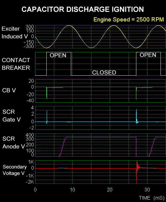
The graph below shows the voltages in the circuit (WITH
SPARK PLUG FITTED):
|


