


|
IN February 1978, Gordon Jennings published an article in CYCLE magazine illustrating the results of using different pre-mix ratios of Premium Unleaded Fuel 98 RON and Castrol 40R oil (based on castor-oil or bean oil) in the engine of a SUZUKI PE250 motorcycle. The results indicated, even with many other factors taken into consideration, that changing from a 30:1 ratio to a 15:1 pre-mix ratio (that is, doubling the oil content) reduced the gum varnish on the piston crown, reduced bore scuffing and increased the power output by 15.7%. Before deciding on the best pre-mix ratio to use, for example 33 : 1 (3%) or 50 : 1 (2%), it should be remembered that most modern semi-synthetic 2-Stroke oils have many qualities and additives that allow higher pre-mix ratios while providing excellent lubrication and freedom from gum varnish. It is therefore recommended that the VeloSoleX S 3800 is run at 50 : 1 (2%) pre-mix ratio if using a Semi-Synthetic oil such as Castrol Scoot-R 2-Stroke Oil or a 100% Fully-Synthetic oil such as Silkolene Pro 2. This ratio represents one fuel cap full of oil to one tank of fuel BUT:
|
|
What can I do about the Front Brake vibrating while braking? |
|---|
|
ON some models of VeloSoleX S 3800, a Caliper type of front brake is used which is sometimes ASSEMBLED INCORRECTLY causing vibration while braking. Dismantle and reassemble correctly using a slight smear of WD40 Oil on the sliding surfaces. WD40 Oil can also be used on chrome wheels and spokes to prevent corrosion but if a Caliper type of front brake is fitted you must clean the rims afterwards with Iso-Propyl Alcohol if the brakes are to work properly. |
|
ON the VeloSoleX S 3800 the black plastic Handlebar Controls sometimes loosen with engine vibration. This problem can be solved as follows:
An alternative solution suggested by Bill of Minnesota, US is to replace the original screw thread with an ISO 6 mm x 1.0 Heli-Coil. |
|
ON the VeloSoleX S 3800 the Fuel Pipes are made from Aluminium which can easily fracture if the Fuel Pipe Unions are over-tightened. To improve reliability, replace the Aluminium Fuel Pipes with Copper Fuel Pipes as follows:
|
|
What can I do about loose Magneto Coil and Lighting Coil bolts? |
|---|
|
THE Magneto Coil and Lighting Coil on the VeloSoleX S 3800 are sometimes secured by bolts held by only 3 or 4 screw threads. These bolts therefore tend to unscrew with the vibration of the engine. The securing of the coils can be improved as follows:
|
|
THE Headlight on the VeloSoleX S 3800 is sometimes a loose fit in its black plastic housing. To make the headlight more secure, squeeze a 5 mm beading of Clear Silicone along the top edge of the Headlight and allow to dry for a few hours before reassembling. Make sure that the Headlight is not pushed too far in otherwise the front bulb contact will short electrically against the top left bolt of the Fuel Pump. |
|
THE Light Switch on the VeloSoleX S 3800 often becomes unreliable with engine vibration as it consists solely of a contact pressing a screw! It can be replaced with a modern Rocker Light Switch (available from most electronic shops) as follows:
NOTE: An illuminated Rocker Light Switch has an extra terminal on one side which must be connected to an Earth connection (eg: Engine Body) for illumination in the "ON" position.
|

|
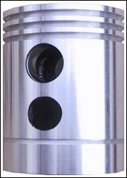
THE Piston on the VeloSoleX S 3800 is already quite a lightweight affair and there is little real advantage to be gained in shortening the piston by removing some of the Piston Skirt. In fact doing so will increase the "rocking" (or "piston slap") and general wear within the cylinder. A shorter piston also requires a smaller gap between piston and cylinder to reduce this effect. Too short a Con-Rod also increases cylinder wear. The reason for reducing the weight of the Piston or Con-Rod is to try to relieve the crank of as much inertial load as possible, thus giving increased Acceleration (lighter components) but this does NOT necessarily mean increased Top Speed. If your engine has the Long Piston shown below (49.45 mm long [measured at the edge] for cylinders made before March 1986 such as the TUM 80 [V1], TUM 80A [V2] or TUM 80A CM 6,5 [V3]), a slight increase in Torque (but not top speed) can be obtained by filing some metal from the Piston Skirt nearest the Inlet Port in the shape of a Crescent 20 mm wide and 2.5 mm high. No more should be removed otherwise the Exhaust Port may be partially open beneath the piston at TDC, allowing the old exhaust gases to enter the crankcase and pollute the fresh mixture. You can undo this modification by replacing the piston with a new one OR by turning the piston 180° around by removing the Crank Pin (Big-End) Bolt and turning the Con-Rod by half a turn before replacing Crank Pin (Big-End) Bolt. To stop the flywheel turning when loosening or tightening the Crank Pin (Big-End) Bolt, fit a Flywheel Clamp. After you have modified the Piston Skirt, drill out the Inlet Port hole in the side of the cylinder using a 9 mm drill.
If your engine has the Short Piston shown below (46.98 mm long [measured at the edge] for cylinders made after March 1986 such as the TUM M 80A CM 6,5 [V4, M = MBK version]), there is no benefit to be gained by filing the Piston Skirt. Also the Inlet Port hole in the side of the cylinder for that engine will already be 9 mm in diameter.
A slight increase in Torque can be obtained if the round Transfer Holes in the piston are filed square (remembering to leave a slight radius in each corner). This increase in Torque is due to a more efficient transfer of the mixture from the crankcase.
With regard to Bore/Stroke Ratio:
The VeloSoleX S 3800 is very slightly "Under-square", a design better for low-RPM torque, but usually not for high-RPM horsepower. "Under-square" motors were much more common in the pre-war period than they are today.
With regard to Rod/Stroke Ratio on the VeloSoleX S 3800:
This high Rod/Stroke Ratio (ie: long Con-Rod) means LESS WEAR to cylinder walls, pistons and piston rings as the combustion forces acting in the downward motion are increased while those toward the cylinder wall are reduced. Also the Piston Dwell Time is longer, meaning that piston remains at the top and bottom of the stroke for a longer time. This allows for better flow of combustion and exhaust gases since the piston accelerates slower in the transition between the "up" and "down" strokes. Intake gases have a longer time to enter the cylinder while exhaust gases are given more time to escape. This means more torque over a wider RPM range. On the other hand, even though the piston accelerates slower in transition, the Maximum Piston Velocity is greater than for a low Rod/Stroke Ratio resulting in some increased component strain. While it is true that piston dwell at TDC is longer with a longer Con-Rod and hence a higher combustion pressure exerted for longer on the piston crown, it should be remembered that maximum torque applied to the crank is when the rod to crank angle is at 90°. When a shorter rod is used, this 90° angle is reached sooner in the engine cycle and therefore at a higher combustion pressure due to the smaller combustion volume at that point. So, for low-speed maximum torque a shorter rod is better, while for high-speed maximum power a longer rod is better (ignoring the increased rod mass for a longer rod). In the end, it must be remembered that the VeloSoleX engine was never designed, regarding component tolerances and general wear, to be a high-revving "sports" engine and many VeloSoleX tuners have found the engine life to be reduced considerably by excessively changing the existing engine parameters. |


|
THE Pedal Axle on the VeloSoleX S 3800 is simply a shaft rotating in the frame. To make sure that it is well-lubricated without necessitating disassembly, drill and tap a hole into the frame tube below the axle centre, clean thoroughly and screw in a Zerk Grease Fitting. Use a shot from a grease gun every few months:
Source: John Ingram, Canada (Solex Owners of America Yahoo! group) |

|
What can I do about broken or worn rivets on the Seat Hinge? |
|---|
|
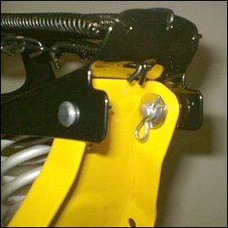
THE Seat Hinge Rivets turn and may wear with time on the VeloSoleX S 3800 but they may be easily replaced with a Clevis Pin of the appropriate size, Washer, Spring & Clip. Cut Clevis Pin to fit, if necessary:
Source: John Ingram, Canada (Solex Owners of America Yahoo! group) |


|
THE Fuel Pump Diaphragm on the VeloSoleX S 3800 is easily replaced:
Symptoms of an old, dry or hard Fuel Pump Diaphragm include lack of power when the throttle is fully open but the power returning when the throttle is partially closed. The Fuel Pump works as follows:
Do not attempt to remove the two glass balls unless:
NOTE: If you do manage to lose one, you will find an similarly-sized ball at the end of a Waterman Pen Ink Cartridge.
|

|
THE Rotor Key inside the rotor centre on a VeloSoleX S 3800 is normally cast with the body. Sometimes the Rotor Key can become worn or sheared off. If this happens a new Rotor Key will need to be fitted as follows:
NOTES:
|

|
THE Condenser on the VeloSoleX S 3800 is quite often unreliable, poorly made, susceptible to humidity and heat and tends to fail at the most inconvenient time! The Capacitance of a Condenser can be measured but it is no guarantee that it will work properly in the hot engine environment while out riding one's VeloSoleX S 3800. For those who want to check the Capacitance of a Non-Polarised High Voltage Dielectric Condenser, one can use one of the following instruments:
If using a Digital meter, the Capacitance of the Condenser should be in the range 0.18 uF - 0.25 uF. If using an Analogue meter, one can still do a basic test of Capacitance and also check that other faults do not exist by following the steps below:
Note: Do not touch the metal prods on the end of the meter leads with your fingers when testing the Condenser, otherwise you will get false readings. The most typical Condenser faults include the Intermittent Open-Circuit Fault due to a loose internal connection caused by engine vibration and the Electric Current Leakage Fault due to the ingress of moisture. Both faults can lead tosome strange engine starting or running symptoms particularly when the engine is hot! The best way to deal with a possibly faulty Condenser is to replace it with a known good one. I recommend replacing the Condenser with a 0.22 uF 1000V DC Metallised Polypropylene Film Non-Polarised Capacitor with a minimum temperature rating of 105°C. This high-quality capacitor is available from most good electronic component stores and has the following features:
|
![]()
VELOSOLEX is a trademark of VELOSOLEX
AMERICA, LLC
e-SOLEX, SOLEX and SOLEXINE
are trademarks of Societie SINBAR
- Groupe CIBLE